Understanding Electrical Schematics: A Step-by-Step Guide
Introduction
Overview of Electrical Schematics
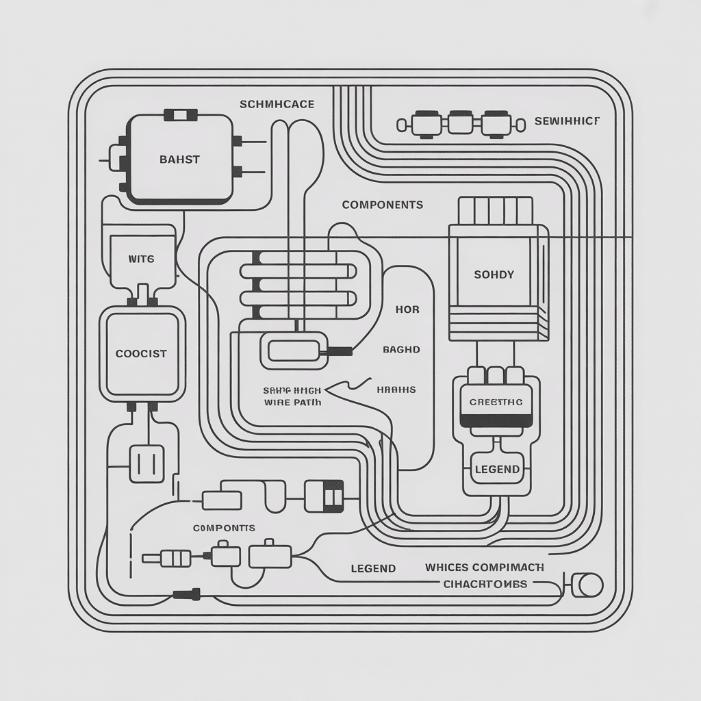
Electrical schematics serve as the blueprints of electrical systems, illustrating how components fit together and function. By utilizing a range of symbols, these diagrams provide a visual representation that can simplify complex circuits. Whether it’s a simple light switch or an intricate control panel, these schematics bring clarity to electrical design.
Importance of Understanding Electrical Schematics
Understanding electrical schematics is crucial for various reasons:
- Troubleshooting: Knowing how to read a schematic helps identify issues quickly.
- Designing: Engineers utilize these diagrams to brainstorm and visualize new ideas or revisions.
- Safety: A proper understanding can prevent electrical hazards.
For instance, when I first encountered a circuit malfunction, referencing the schematic enabled me to pinpoint a faulty component quickly, saving both time and resources. In electric work, the ability to interpret these diagrams can often mean the difference between a successful repair and a potential disaster.
Basics of Electrical Schematics
Symbols and Abbreviations
One of the keys to mastering electrical schematics lies in understanding the various symbols and abbreviations. Each symbol represents a specific component, making it essential for anyone working with electrical systems. Familiar symbols include:
- Resistors: Zigzag lines
- Capacitors: Two parallel lines
- Diodes: A triangle pointing to a line
These symbols form the building blocks of circuit diagrams. When I first learned to read schematics, recognizing these symbols felt like cracking a code—it opened doors to deeper insights into circuit functionality.
Understanding Circuit Diagrams
Circuit diagrams take this foundational knowledge further by showing how components connect and interact. These diagrams do not depict the physical layout but instead focus on the electrical relationship. Here’s what to look for:
- Connections: Lines represent wires and how components connect.
- Nodes: Points where wires meet signify junctions.
- Power source: Typically depicted at the beginning of a diagram, highlighting where energy originates.
As I navigated my first circuit diagram, the abstract representation helped me visualize how energy flowed, enabling me to troubleshoot with greater efficiency. A solid grasp of these basics is essential for anyone looking to dive deeper into electrical schematics.
Reading and Interpreting Electrical Schematics
Identifying Components and Connections
Once familiar with the symbols and basic structure, the next step is to master reading and interpreting electrical schematics. This process involves identifying components and understanding their connections. Key elements to note include:
- Components: Look for resistors, capacitors, transistors, and other parts represented by their respective symbols.
- Connections: Lines indicate how components are linked; a dot where lines meet often signifies a connection.
I vividly recall the first time I traced a fault in my home’s wiring by following the schematic. By pinpointing each component along the path, I could understand the entire circuit, leading me to the source of the problem!
Analyzing Power Supplies and Grounding
A crucial aspect of interpreting schematics involves analyzing power supplies and grounding. These elements ensure the circuit operates safely and effectively. Here’s what to consider:
- Power Supplies: Identify where the power originates, often shown as a battery or an AC source. Understanding the voltage is critical for safe operation.
- Grounding: Typically represented by a set of horizontal lines, grounding ensures excess voltage is diverted, promoting safety and stability in circuits.
When I tackled a complex piece of equipment, understanding power supply layouts helped me determine the correct input voltage required. By effectively analyzing these critical components, I ensured optimal performance and safety, reinforcing the importance of thorough schematic examination.
Common Electrical Schematic Diagrams
Single Line Diagrams
Single line diagrams (SLDs) are essential for simplifying complex electrical circuits into a more manageable format. These diagrams utilize a single line to represent power distribution and connections, allowing engineers and electricians to grasp system layouts quickly. Key features of SLDs include:
- Clarity: They eliminate unnecessary details, focusing on mains and major components.
- Simplified Representation: All three phases in a three-phase system are represented by one line, making it easier to visualize power flows.
I remember attending a workshop where we analyzed single line diagrams for a commercial building. The clarity of these diagrams made understanding the entire power system straightforward, allowing us to evaluate potential upgrades effectively.
Wiring Diagrams
Wiring diagrams take a different approach, providing detailed information on how to physically connect electrical components. Unlike single line diagrams, they feature:
- Detailed Connections: These diagrams offer a comprehensive view of how wires should be run, emphasizing the location and connection of each component.
- Physical Layout: They illustrate the devices’ locations, making them invaluable for installation and troubleshooting.
When I was tasked with wiring a new outdoor lighting system, referencing the wiring diagram made the process seamless. Understanding the exact connections required allowed me to complete the project efficiently and confidently. Familiarity with these common schematic types enriches one’s ability to work with electrical systems effectively.


